In the IPv6 over IPv4 tunneling migration strategy, isolated IPv6-only networks are connected using IPv4 tunnels. With overlay tunnels, IPv6 packets are encapsulated within IPv4 packets so that they are sent over the IPv4 WAN. Overlay tunnels can be configured between border devices or between a border device and a host; however, both tunnel endpoints must support the IPv4 and IPv6 protocol stacks. The advantage of this method is that you do not need separate circuits to connect the IPv6 isolated networks.
A disadvantage of this method is the increased protocol overhead of the encapsulated IPv6 headers. Furthermore, overlay tunnels reduce the maximum transmission unit (MTU) by 20 octets.
Manual Configured Tunnels and GRE Tunnels
As defined in RFC 4213, manually configured (static configuration) tunnels are configured with IPv4 and IPv6 addresses for tunnel source and destination. Tunnels can be built between border routers or between routers and hosts. A tunnel is equivalent to a permanent link between two IPv6 domains over an IPv4 backbone. The border routers at each end of the tunnel must support both IPv6 and IPv4 protocol stacks.
IPv6 packets can also be carried over IPv4 Generic Routing Encapsulation (GRE) tunnels for stable connectivity between two IPv6 domains. A GRE tunnel is not tied to a specific passenger or transport protocol and can support other Layer 3 protocols (such as IS-IS) over the same tunnel. Because GRE has a protocol field, it can identify the passenger protocol (such as IPv6 or IS-IS); therefore, it is advantageous to tunnel IS-IS and IPv6 inside GRE.
Automatic Tunnel Mechanisms
Automatic tunnel mechanisms include the following:
- 6to4
- 6RD
- ISATAP
6to4 Tunnels
RFC 3056 specifies the 6to4 method for transition by assigning an interim unique IPv6 prefix. 2002::/16 is the assigned range for 6to4. Each 6to4 site uses a /48 prefix that is concatenated with 2002. An automatic 6to4 tunnel may be configured on a border router of an isolated IPv6 network to create a tunnel over an IPv4 infrastructure to a border router in another IPv6 network. The border router extracts the IPv4 address that is embedded in the IPv6 destination address and encapsulates the IPv6 packet in an IPv4 packet with the extracted destination IPv4 address. The destination router extracts the IPv6 packet and forwards it to the IPv6 destination.
Figure 2-12 shows a network using IPv4 tunnels. Site A and Site B both have IPv4 and IPv6 networks. The IPv6 networks are connected using an IPv4 tunnel in the WAN.
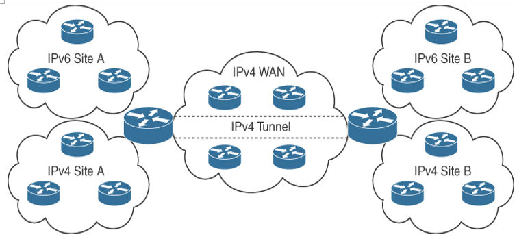
Figure 2-12 IPv6 over IPv4 Tunnels