Deployment of IPv6 can be done in one of the following models:
- Dual-stack model: IPv4 and IPv6 coexist on hosts and on the network.
- Hybrid model: This model uses a combination of ISATAP or manually configured tunnels and dual-stack mechanisms.
- Service block model: This model uses a combination of ISATAP and manually configured tunnels and dual-stack mechanisms.
Dual-Stack Model
In the dual-stack model, devices and the network routers and switches all run both IPv4 and IPv6 protocol stacks. The applications on the devices decide which stack to use to communicate with destination hosts. Alternatively, DNS is used to decide which stack to use. A DNS AAAA RR return uses IPv6, and a DNS A RR return uses IPv4. Because most mature operating systems now support IPv6, this is the preferred technique for transition to IPv6. Figure 2-14 shows a dual-stack network where both protocols reside. Older IPv4 sites that have not migrated to the dual-stack model can communicate throughout the network with other IPv4 devices.

Figure 2-14 Dual-Stack Deployment Model
Hybrid Model
The hybrid model uses a combination of transition mechanisms, depending on multiple network criteria, such as number of hosts, IPv6-capable hardware, and location of IPv6 services. The hybrid model can use these transition mechanisms:
- Dual-stack mechanism
- ISATAP
- Manually configured tunnels
The hybrid model can be used to tunnel a dual-stack host on an IPv4 access layer to an IPv6 core. As shown in Figure 2-15, the dual-stack computer establishes an ISATAP tunnel to the core layer to access services from the dual-stack server on the right.
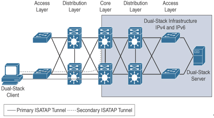
Figure 2-15 IPv6 Hybrid Model with ISATAP Tunnel
Another scenario is to tunnel dual-stack distribution layers over an IPv4-only core. As shown in Figure 2-16, the dual-stack computer on the left can access the dual-stack server on the right via the manually configured tunnels. Multiple tunnels are configured to provide redundancy and load balancing.
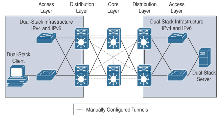
Figure 2-16 IPv6 Hybrid Model with Manually Configured Tunnels
Service Block Model
In the service block model, a centralized layer that services dual-stack devices is created with tunnels manually configured between the distribution layer and the service block. Dual-stack hosts also connect via ISATAP tunnels. In Figure 2-17, the dual-stack client on the left connects to the service block to establish connectivity with the dual-stack server on the right.
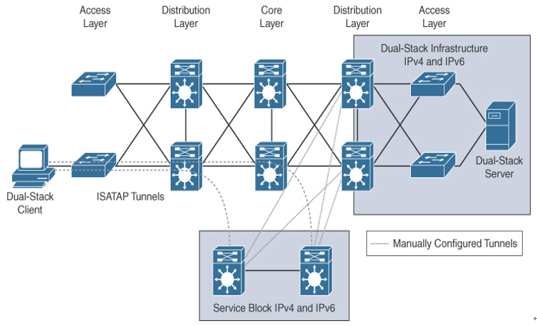
Figure 2-17 Service Block Deployment Model